Ventilation dampers. What is the goal of the ventilation device testing?
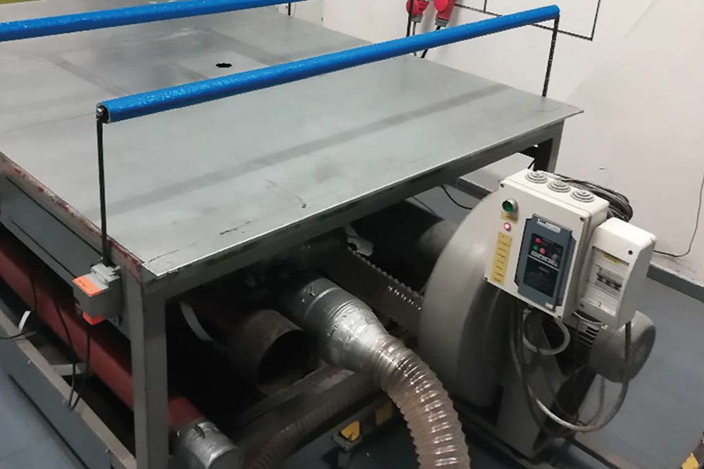
Test stand for testing damper tightness
Autor

Izabela Tekielak-Skała
Head of the CFD Research and Analysis Department in the comapny SMAY Sp. z o.o
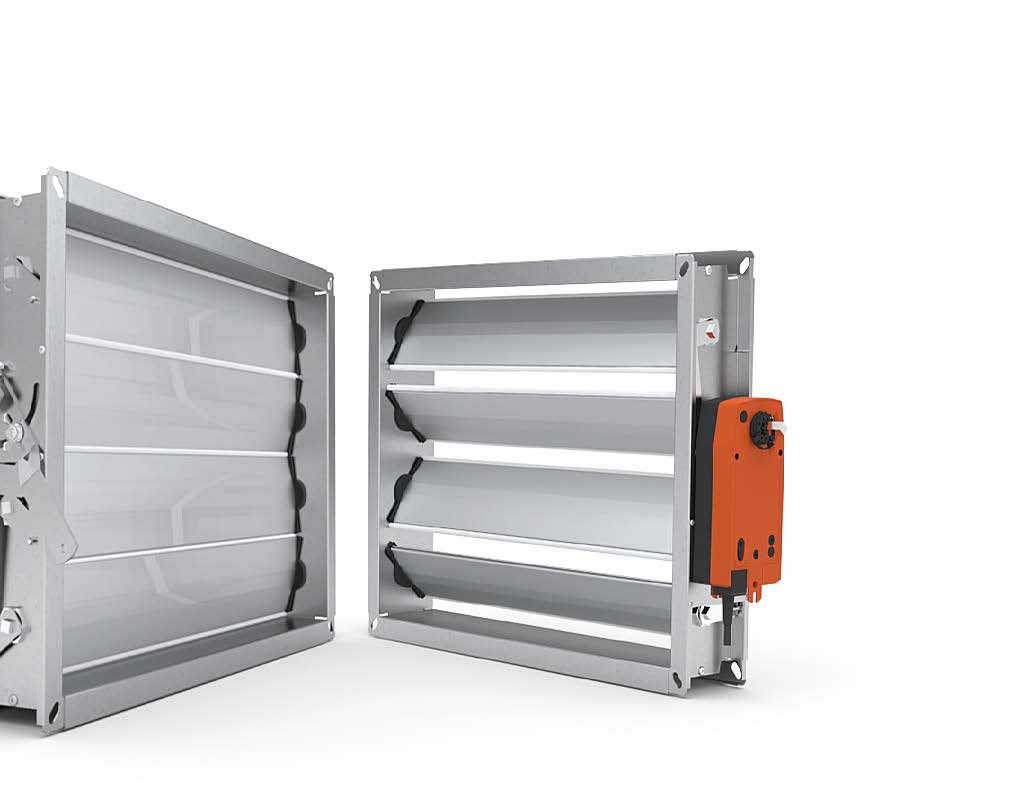
Dampers are one of the main components of ventilation systems. When installed in the ducting, they make it possible to adjust and cut the airflow off. But how do we know the parameters of ventilation dampers?
Well, at the SMAY factory laboratories we have professional test stands used to perform tests of damper basic parameters, such as tightness, aerodynamic characteristics or torque.
All the tests are carried out in accordance with PN EN 1751:2014 [1], on the basis of procedures developed in the Research Department and laboratory. Below, we described selected parameters of dampers and their impact on the installation operation.
Testing ventilation devices according to SMAY
The damper tightness affects the total level of tightness of the installation, which to a certain degree translates into required capacity of air supply fans. Ventilation dampers are tested for tightness of the baffle and, independently, the enclosure. In order to explain the significance of damper baffle tightness, let us consider an example of a device of 0.5 m2 surface area and the integrity rating 4 (baffle tightness) that operates in a system with working pressure of 300 Pa. Such an integrity class of the damper means the air leak to the other side of the damper baffle does not exceed 5.5 m3/h, whereas lowering the standard down to the integrity rating 2 would cause air leaks of around 125 m3/h. Further tightness lowering down to the integrity class 1 would cause leaks exceeding 600 m3/h.
As can be seen in the calculations above, lowering the integrity rating of the baffle down from 4 to 2 would increase the air stream over 20 times, while lowering the baffle integrity rating down from 4 to 1 would increase the air stream flowing through the leaks in the baffle over 100 times! Similarly, lowering the integrity rating of the enclosure down translates into lowering the volume of air flowing out of the system uncontrollably. Our class C damper will show leaks through the enclosure at the level of around 0.9 m3/h, while for class A this value will be nine times higher, that is approx. 7.9 m3/h.
Above, we have only presented the analysis for a single damper of 0.5 m2 surface area, and, as is known, there may be several or even tens of dampers in one ventilation system. Using dampers of a higher integrity class makes it possible to lower the air volume flowing through the leaks, which may result in lowering the required capacity of the fans operating in the system. Lower capacity may also translate into lowering the fans’ power, and — consequently — energy savings.
Ventilation dampers and the pressure loss
Another important damper parameter is the pressure loss that occurs when the air flows. The pressure loss when the air flows is determined for a fully open damper. The change of the damper baffle position causes higher loss, which may be used during adjustment of already existing systems. As a result of the test carried out in accordance with the standard [1] we should obtain a discharge coefficient (Cd), which is inversely proportional to a local resistance coefficient (ξ):

By learning the local resistance coefficient we can determine the pressure loss of the damper, which depends on the air flow velocity squared (w2), density (ρ) and resistance coefficient (ξ):

The resistance of the damper affects the total pressure loss in ducting, which in turn translates into required compression ratio of a fan. Parameters described above can only be determined during laboratory tests. SMAY has its own laboratories equipped with test stands designed for determining the values of parameters being discussed. Our experienced laboratory team has been testing ventilation products for years. One of the first stands in the laboratory designed for testing dampers was a stand for tightness tests, consisting of a table with a special chamber and a fan, as well as a metering system for pressure and volumetric air flow measurements (Fig. 2). The stand was made in accordance with the standard. It makes it possible to test the tightness of damper enclosures and baffles in a closed position. Later, the laboratory was expanded with stands for resistance and torque tests, consisting of fans, air flow straighteners and appropriately long straight test ducts. These stands are also equipped with proper devices for pressure, volumetric air flow and torque measurements.
As the first manufacturer in Poland, SMAY has obtained the National Technical Assessments for single- and multi-blade dampers, issued by the Technical Assessment Department of the National Research Institute. SMAY, as a conscious manufacturer, puts emphasis on the conformity its products with the stated parameters. The company is aware of the fact that one-time tests (a type test) may be not sufficient. Many factors may affect the device performance, such as manufacturing technology or the final shape of product. However, there are less obvious, seemingly insignificant factors, such as the change of a supplier of device construction materials or a new employee responsible for the product mounting. Tests of ventilation devices and continuous product control carried out at SMAY make it possible to find all deviations at an early stage. This in turn makes it possible to quickly correct nonconformities and to keep the required operating parameters.
Safety Way: an innovative differential pressure system – escape routes free from smoke and fire – highest degree of protection.
The Safety Way differential pressure system is a solution designed for multi-storey buildings:
• iSWAY-FC® differential pressure product for smoke and heat control systems;
• Innovative predictive algorithm;
• Anti-Frost system that endures even the most extreme weather conditions;
• 24-hour automatic test of all the components;
• Automatic adaptation to changing service conditions;
• Communication between individual components of the set and continuous tracking of all components (regulators, remote pressure sensors, etc.);
• Continuous measurement of the set value of static differential pressure between the protected and reference zones by the P-MAC(F) sensor.
Do you want to know more? Visit our BLOG. Our experts will provide you with a full knowledge base on ventilation and fire protection.
Do you need advice? Contact our advisor department.