Air intakes and their water rejection performance
Air intakes are designed to collect external air. Depending on the mounting location it is possible to single out wall, roof air intakes and air inlet towers.
Wall air intakes are often part of a building façade. Usually they are rectangular, but they might be circular as well. The air intake opening is fitted with blades and additionally with a mesh, which prevents birds, rodents, and leaves from getting into the system.
The roof air intakes have a circular or rectangular basis. Sometimes in this installation variant, the device might be secured with a mesh only. Depending on the version, air may flow into the system from several sides of the air intake (one to four sides).
Air inlet towers, also known as standalone inlet vents, are being mounted near buildings, most often as reinforced concrete or masonry structures finished with a rain cover. It sometimes happens that the equivalents of air vent rectangular louvres are being mounted in the intake openings.

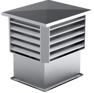
Figure 1. Exemplary air intake – the air vent rectangular louvre version (a) and the roof version with a rectangular basis (b)
According to Paragraph 152, Section 1 of Technical Conditions for Buildings and their Location [1] “Air intakes in ventilation and air-conditioning systems shall be secured against precipitation and wind […]”. In practice, it is very hard to decide the place for the air intake installation, which satisfies this condition. Therefore, it is expected that the structure of the air intake itself will prevent water from penetrating the system. In order to assess the louvre water rejection performance, it is possible to use the methodology presented in EN 13030 – Ventilation for buildings. Terminals. Performance testing of louvres subjected to simulated rain [2].
Air intakes vs. performed tests
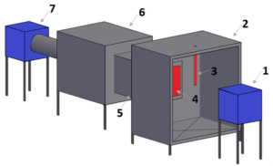
The rainwater ingress tests on the air intakes shall be carried out at a three-section station (the weather, collection, and aerodynamic section). The detailed description of the station can be found in Methodology for Testing the Air Intake Efficiency for Water Retention [3] paper. We can single out the following basic elements of the measurement station:
• The weather simulation chamber
This section is being used for simulating the influence of wind and rain on the air intake under test. It is necessary to reproduce 13 m/s wind at the distance of 1 m from the device. The simulated rainfall should be characterized by the specific, measured stream. The water drop spray angle is also relevant.
• The collection chamber
In this section the water getting through the air intake under test is being collected during the examination. The amount of water collected during the test in this chamber makes it possible to determine the water rejection performance of a given air intake. The more water gets into the collection chamber, the lower is the air intake water rejection performance.
• The aerodynamic chamber
The goal of this section is to equalize the airflow before the measuring element The air volumetric flow can be measured by means of an intake cone placed in this chamber or any other device which assures the adequate precision of measurement.
1 – wind simulating fan
2 – weather simulation chamber
3 – rain simulation system
4 – air intake under test
5 – collection chamber
6 – aerodynamic chamber
7 – fan for airflow forcing
Figure 2. Measurement station outline
Standard [2] provides relationship, which makes it possible to determine the air intake water rejection performance. Four water rejection performance classes have been defined for the air intakes. Class A is the best, while class D is the worst. The last one means that the water rejection performance is under 80%. Detailed ranges of particular classes can be found in Table 1.
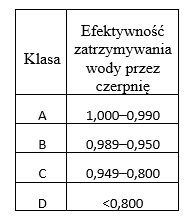
Table 1. Air intake water rejection performance classes
During testing the air intake water rejection performance Standard [2] imposes the necessity of carrying out the test for multiple airflows. The air intake might be rated for each examined flow in different class. Standard [2] relates the air volumetric flow to the air intake core surface area, the size of which is determined as the product of the minimum height and width of the intake opening, when the blades are removed.
Air intakes – nothing but practise
The increase in the velocity of air flowing between the air intake blades has usually been translated into the increase in the amount of water drawn into the system as well. As a consequence, the water rejection performance displayed by a given air intake has been down. The lower the velocity of air flowing between the air intake blades, the easier it is to achieve satisfying working parameters of the device, which means low resistance and high water rejection performance. It is worth pointing out that the air intake resistance and water rejection performance are strongly connected with each other.
The air intakes characterized by low resistance very often show poor water rejection performance. High water rejection performance most often means significant resistance of the device.
Depending on the design of the air intake, it is possible to achieve various operating parameters of the device. There is no single constant velocity, at which water will not be drawn into the system through air intakes of various design. What is important, different velocities might be pivotal for acceptable (or unacceptable) water suction into the system through the air intake. Because of that, it is very important to select devices with the specific parameters for a given duty point.
In order to compare parameters of different devices during selection it is very important to test them in the same way. No other approach makes it possible to determine which of the devices performs the best. If different reference standards are being used during the measurements, it might result in completely different working parameters having nothing more in common but a name.
It is also worth noticing that the reference velocity is very important for the air intake water rejection performance test. Although the Standard clearly defines how to determine the velocity, it is not mandatory to use the same velocity in the data presented in catalogues available on the manufacturer websites. And quite often, due to the necessity of showing other parameters as well, it is more convenient to present this parameter in a different way.
Therefore, while selecting an air intake, besides the class itself, you should pay special attention to the “meaning” of the velocity for which the given class requirements are met. Differences in the water rejection performance achieved by the exemplary air intake depending on the assumed way of data presentation are shown in Chart 1. A line, which shows the water rejection performance in relation to the velocity at the air intake core surface (blue line), is determined according to Standard [2]. The results of the same test related to the free cross-section area velocity are shown with the red line.
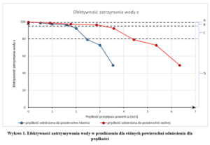
If the user, when analysing data, does take into consideration that the velocities are related to the completely different surfaces, he/she may take the view that two products have different properties – even though in fact they operate identically, and only the results of their actions are presented in different ways. Table 2 shows boundary velocities, which can be read for individual classes from the example presented in Chart 1.
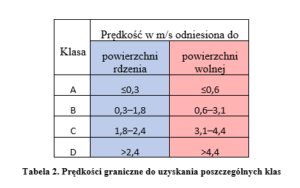
As can be seen in Table 2, the velocity limits are completely different, but it is just the result of a different approach to the surface the airflow is related to. By not taking into account the type of the reference surface used for the velocity calculations, you may falsely assume that the results presented in Table 2 apply to different air intakes, and that the “first” one performs worse, because at a lower velocity it gains the worse rating comparing to the “second” one. In the presented example, the surface area of the core of the element under test was equal to 0.89 m2, and the free surface area was equal to 0.50 m2. In the end it gives identical airflows, and different velocities have purely been the result of different reference cross-section surfaces.
Air intakes – the conclusion
In order to assess the louvre water rejection performance, it is possible to use the methodology presented in EN 13030. Four water rejection performance classes are singled out (from A to D, where D is the lowest rating). The velocity the results are related to, is very significant for the air intake water rejection performance.
There is no single constant velocity, at which water will not be drawn into the system through air intakes of various design. Determining the working parameters always requires analysis of the data provided by the manufacturer. The air intakes with low resistance most often show low water rejection performance. High water rejection performance most often translates into significant resistance of the device.
When selecting the air intake it is necessary to determine which of the parameters is significant, and on this basis pick a device, which meets the demands. However, it is worth noticing that lower values of the air flow per air intake surface area very often translates into better working parameters (lower resistance, higher water rejection performance class). Therefore, if both low resistance and water rejection performance are essential, then the increase in dimensions of a given air intake, while maintaining the air flow, might improve the device performance.
[1] The Ordinance of the Minister of Economic Development and Technology of 16 September 2020 amending the Ordinance on Technical Conditions for Buildings and their Location.
[2] EN 13030 Ventilation for buildings – Terminals – Performance testing of louvres subjected to simulated rain.
[3] M. Borowski, J. Halibart, M. Karch, I. Tekielak-Skałka, Methodology for Testing the Air Intake Efficiency for Water Retention, “Ciepłownictwo, Ogrzewnictwo, Wentylacja” 54/11, 2020, pp. 24–27.
Autor

Joanna Halibart
Deputy Head of the CFD Research and Analysis Department

