Design Solutions for Overpressure Systems. Conformity to PN-EN 12101-6, Part II

Autor

Rafał Polichnowski
Assistant Commercial Director – SMAY Sp z o.o
In the last article, we discussed the B class pressure differential system and the airflow rate criterion for the air supplied to a zone engulfed in fire, which is 2 m/s in case of the gravitational exhaust ventilation. Now, we will focus on a solution based on the mechanical exhaust ventilation, the purpose of which is extracting hot smoke from a zone engulfed in fire.
The PN-EN 12101-6 standard defines six classes of pressure differential systems: A, B, C, D, E and F. A designer working with an expert should establish which class to use in a given building. Depending on the choice, certain system design criteria introduced by the standard must be met. In total, we can distinguish 5 versions of the system based on the mechanical exhaust ventilation. Today, we will discuss three of them while the subsequent two will be described in the next article.
Mechanical Exhaust Ventilation
With this solution we need to seek the lowest possible underpressure in the zone engulfed in fire when the door to the entrance hall is closed, because the underpressure value directly affects the door opening force, which cannot exceed 100 N.
a) Let’s assume that the entire air is supplied to the staircase (Figure 4). The air flowing at a rate of 14,400 m3/h passes through the doorway between the staircase and entrance hall, and then through the doorway between the entrance hall and the zone engulfed in fire. Subsequently, the air is being transported out of the building by the provided smoke ventilation system. An automatic opening window of 2 m2 effective area is planned for smoke exhaust compensation when the door is closed. Let’s analyse the resistance and system output generated with this airflow criterion.
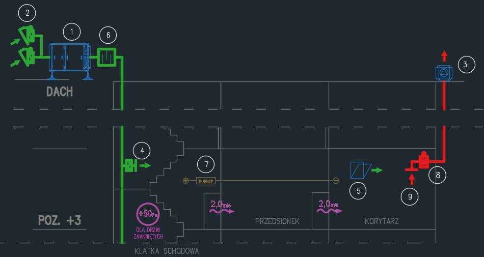
Figure 4. Air flowing through the doorway from one area to another.
LEGEND:
- 1. iSWAY air supply unit
- Damper-controlled double supply louvre system
- SEFL/REF smoke exhaust fan
- STW/GA air supply grille with a damper
- Automatic opening window with an actuator — smoke exhaust compensation feature
- TAP rectangular acoustic silencer
- P-MACF remote pressure sensor
- KWP-P-E fire ventilation damper with an actuator
- SDS-STW smoke exhaust grille
The air flowing through the doorway from one zone to the other at a rate of 2 m/s generates a resistance of 6 Pa (Table 1). Since we have two doorways, the total resistance equals 12 Pa. We use mechanical exhaust ventilation. Therefore, no additional resistance is present in this case. The total resistance thus amounts to 12 Pa. We can state that all other openings in the staircase require the resistance of at least 12 Pa so that the air passes through an open door in the direction of the exhaust grille of the smoke ventilation system.
The biggest opening in the staircase is an open emergency exit door outside the building. Let’s assume that its area is 2 m2. In order to ensure a flow resistance of 12 Pa, the airflow rate must equal 2.9 m/s. It seems that — considering that the air should flow to the staircase at a rate of 2 m/s — we must supply 20,880 m3/h (we shall not include any other leaks in the staircase in this analysis). Therefore, the total amount of air required to meet the airflow rate criterion with such a mechanical exhaust is 14,400 m3/h + 20,880 m3/h = 35,280 m3/h. Now, we should consider a proper placement of air supply points in the staircase in order not to exceed door opening force at any storey, i.e. 100 N.
ATTENTION!
In case of the pressure difference criterion leaks in the staircase may be significantly lower (Figure 1). The fan must therefore supply extremely different quantities of air depending on the number of open and closed doors. Only devices with valid certificates stating fan working ranges and system response times should be used. Additionally, the smoke ventilation system for the zone engulfed in fire shall be designed for the output rate of 14,400 m3/h.
c) Let’s assume that the entire air is being supplied to the entrance hall (Figure 6). The air flowing at a rate of 14,400 m3/h passes through the doorway between the entrance hall and the zone engulfed in fire. Subsequently, the air is being transported out of the building by the provided smoke ventilation system. A hole in the wall between the zone engulfed in fire and the entrance hall with an effective area of 1 m2 is planned for smoke exhaust compensation when the door is closed. In order to maintain the 2 m/s velocity of air flowing through the door, we need to supply additional 7,200 m3/h of air to the entrance hall. In total, we supply 14,400 m3/h + 7,200 m3/h = 21,600 m3/h of air to the entrance hall. Let’s analyse the resistance and system output generated with this airflow criterion.
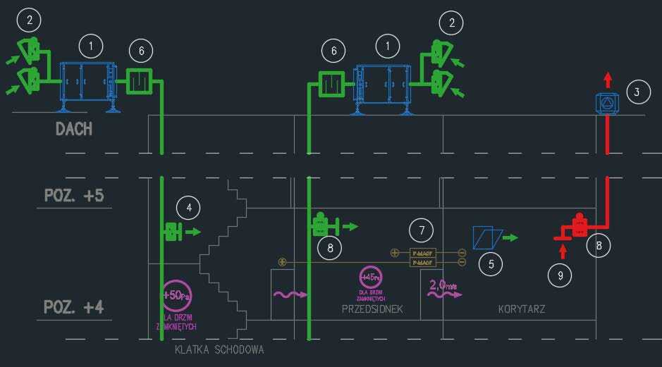
LEGEND:
- iSWAY air supply unit
- Damper-controlled double supply louvre system
- SEFL/REF smoke exhaust fan
- STW/GA air supply grille with a damper
- Automatic opening window with an actuator — smoke exhaust compensation feature
- TAP rectangular acoustic silencer
- P-MACF remote pressure sensor
- KWP-P-E fire ventilation damper with an actuator
- SDS-STW smoke exhaust grille
The air flowing through the doorway from one zone to the other at a rate of 2 m/s generates a resistance of 6 Pa (Table 1). As we have a single doorway, the total resistance equals 6 Pa. We use mechanical exhaust ventilation, so no additional resistance is present in this case. The total resistance thus amounts to 6 Pa. We can state that all openings in the staircase require a resistance of at least 6 Pa so that the air passes through an open door in the direction of the exhaust grille of the smoke ventilation system.
The biggest opening in the staircase is an open emergency exit door outside the building. Let’s assume that its area is 2 m2. In order to ensure a flow resistance of 6 Pa, the airflow rate must equal 2.0 m/s. It seems that — considering that the air should flow to the staircase at a rate of 2 m/s — we must supply 14,400 m3/h (we shall not include any other leaks in the staircase in this analysis). Therefore, the total amount of air required to meet the airflow rate criterion with such a mechanical exhaust is 14,400 m3/h + 14,400 m3/h = 28,800 m3/h. Now, we should consider a proper placement of air supply points in the staircase in order not to exceed door opening force at any storey, i.e. 100 N. This also applies to the door in the entrance hall to the zone engulfed in fire. Air is supplied to the entrance hall and staircase by two independent devices.
ATTENTION!
In case of the pressure difference criterion leaks in the entrance hall and staircase may be significantly lower (Figure 1). The fan must therefore supply extremely different quantities of air depending on the number of open and closed doors. Only devices with valid certificates stating fan working ranges and system response times should be used. Additionally, the smoke ventilation system for the zone engulfed in fire shall be designed for the output rate of 14,400 m3/h.
LEGEND:
- iSWAY air supply unit
- Damper-controlled double supply louvre system
- SEFL/REF smoke exhaust fan
- STW/GA air supply grille with a damper
- WKP-O-E-T transfer damper with an actuator
- TAP rectangular acoustic silencer
- P-MACF remote pressure sensor
- KWP-P-E fire ventilation damper with an actuator
- SDS-STW smoke exhaust grille
The air flowing through the doorway from one zone to the other at a rate of 2 m/s generates a resistance of 6 Pa (Table 1). As we have a single doorway, the total resistance equals 6 Pa. We use mechanical exhaust ventilation, so no additional resistance is present in this case. The total resistance thus amounts to 6 Pa. We can state that all openings in the staircase require a resistance of at least 6 Pa so that the air passes through an open door in the direction of the exhaust grille of the smoke ventilation system.
The biggest opening in the staircase is an open emergency exit door outside the building. Let’s assume that its area is 2 m2. In order to ensure a flow resistance of 6 Pa, the airflow rate must equal 2.0 m/s. It seems that — considering that the air should flow to the staircase at a rate of 2 m/s — we must supply 14,400 m3/h (we shall not include any other leaks in the staircase in this analysis). Therefore, the total amount of air required to meet the airflow criterion with such a mechanical exhaust ventilation is: 14,400 m3/h + 21,600 m3/h = 36,000 m3/h. Now, we should consider a proper placement of air supply points in the staircase in order not to exceed door opening force at any storey, i.e. 100 N. This also applies to the door in the entrance hall to the zone engulfed in fire. Air is supplied to the entrance hall and staircase by two independent devices.
ATTENTION!
In case of the pressure difference criterion leaks in the staircase may be significantly lower (Figure 1). The fan must therefore supply extremely different quantities of air depending on the number of open and closed doors. Since the smoke exhaust compensation is carried out by the air supplied to the entrance hall, in case of the pressure difference criterion (Figure 1) the output rate is 21,600 m3/h. The air supply device supplies the constant amount of air at all times — when the door is both closed and open. Only devices with valid certificates stating fan working ranges and system response times should be used. Additionally, the smoke ventilation system for the zone engulfed in fire shall be designed for the output rate of 21,600 m3/h.
Safety Way: an innovative differential pressure system – escape routes free from smoke and fire – highest degree of protection.
The Safety Way differential pressure system is a solution designed for multi-storey buildings:
• iSWAY-FC® differential pressure product for smoke and heat control systems;
• Innovative predictive algorithm;
• Anti-Frost system that endures even the most extreme weather conditions;
• 24-hour automatic test of all the components;
• Automatic adaptation to changing service conditions;
• Communication between individual components of the set and continuous tracking of all components (regulators, remote pressure sensors, etc.);
• Continuous measurement of the set value of static differential pressure between the protected and reference zones by the P-MAC(F) sensor.
Do you want to know more? Visit our BLOG. Our experts will provide you with a full knowledge base on ventilation and fire protection.
Do you need advice? Contact our advisor department.