Errors in mounting regulators. How to avoid mistakes that could affect further operation of the system?

Despite the growing awareness among designers and installers as to the operation of ventilation systems, still there are many cases of air flow regulators installed in a way that prevents their proper operation. Unfortunately, most frequently the problem of improper installation is revealed only after the user or inspector has made a complaint concerning the amount of air supplied to occupied rooms. Such claims are most often voiced when the room quickly becomes stuffy or when draughts can be felt. The problems with proper air distribution are even less frequently identified at the stage of measurement records inspection before the commissioning of a facility because defects are simply hidden and kept secret.
Errors in mounting regulators that should be avoided. Reliable ventilation system measurements and the result analysis are key to solving the problem
Mistakes made during the preparation of measurement records for the installation most often result from the inability to perform the measurements, insufficient amount of time to prepare the reports, and at times from the mere dishonesty of people performing the measurements and their wish to quickly perform and hand over the system at the recipient’s expense. This is one of many reasons why in case of any problems with the volumetric air flow rate value in the final component of the system quite often users blame the installed air flow regulator and they report the problem to the regulator’s manufacturer, claiming that the device is malfunctioning. Few users first check the installation correctness of the regulator, the way the ventilation system has been made, the static pressure available in a given system branch or, for instance, the supply voltage or control signal for the devices. In fact it is the manner of the devices’ operation and assembly that we verify in the first place to examine the problem and find a solution.
Knowledge of available solutions will help you to eliminate problems
Undoubtedly, a frequent cause of problems within a facility is a significant reduction in the space available for installation, which stems from the manner these facilities are designed or the requirement to correct the existing buildings. We take those matters into consideration when designing and creating ventilation systems. We try to provide our clients with professional advice and offer solutions customised to the potential of a given facility. Still, the most important issue is to know the available solutions and actions that prevent or at least minimize the results of incorrect installation. At this point, it should be emphasized that the individual types of the CAV and VAV regulators differ both in terms of their operating parameters, such as air flow range, acceptable operating pressure, flow resistance or tightness and in terms of their adjustment accuracy and minimum recommended distances from any bends, tees, etc. Errors in mounting regulators resulting from incorrect installation depends on the class of the device applied and the control systems used within it as well as the component used for volumetric flow measurement.
Plus, it is worth paying attention to the control error declared by the producer for a given unit: whether it is expressed in relation to the flow rate setpoint or to the Vnom parameter. The declaration of the “of Vnom” value often means that the control error must be counted from the maximum flow rate that the unit is able to control. For example, for a device with the operating range of 50–300 m3/h, the error at 10% Vnom should be interpreted as 10% of 300 m3/h for each individual setpoint. The above means that the error is fixed and can amount to 30 m3/h, i.e. for a flow rate of 50 m3/h the error value ranges from 20 to 80 m3/h. As a result, the error versus the setpoint of 50 m3/h is not 10%, but even 60%. Thus, we can see the first aspect that should be considered, namely control accuracy and the manner it is defined. Naturally, the cheaper the device, the simpler the control system, and automatically – less precise and more exposed to errors, especially if installed incorrectly.
How to choose a regulator best suited to the facility?
First of all, we should examine the manufacturers’ offer and their applied division or grouping of the available regulators. The devices can be classified as follows:
The CAV in-duct regulators – the simplest control devices. They do not require electric power supply, but they limit the flow rate setpoint to the greatest extent (the device is moved directly into the duct – i.e. the spiro pipe – please note that the air flow rate setpoint must be adjusted beforehand). They usually pose the highest requirements concerning the straight sections upstream of the device. If the required distances are not kept, it is difficult to counteract the consequences of major control errors. Plus, in order to verify the correctness of the setpoint after any irregularities have been revealed, the user has to dismantle a part of the system. In this case the control error is often declared as % Vnom. These devices are widely used due to their greatest advantage: the price.

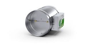
Constant air flow regulator KCR-R
Important note – the CAV regulators, even if equipped with an electric actuator, cannot be perfectly sealed by the actuator. This results from the operation principle of their control mechanisms and their acceptable calculated operational resistance values. In this type of devices the actuator is not moved by the baffle’s axis, but by the flow-rate setting mechanism only.
2. The CAV regulators for standard installation – these units are equipped with a much more advanced, mechanical control system, therefore they ensure higher precision and a wider range of selectable flow rate setpoints. The mechanical control system is based on the basic mechanics principles and includes a spring system and a vibration damper. This type of regulator can be additionally equipped with an electric actuator for changing the flow rate setpoint.
The advantages of these products include: the possibility of setting any flow rate value within the operational range (obviously considering the accuracy of the setting scale), quick setpoint verification as well as the possibility of changing the setpoint without tampering with the system’s structure. In addition, most regulators of this type can work in any position.

Constant flow controller CAV with circular cross section RCP-R
3. The VAV regulators based on measuring strips or orifices – the devices of the widest application range. The control system is an electric control actuator, while the measuring strip enables precise measurement of volumetric air flow. However, these regulators are limited in terms of the minimum pressure increase. They are installed along the duct sectional axis, which increases the risk of pollution. Plus, devices equipped with this type of pressure increasing components are sensitive to the straight sections applied in the system. The device enables the user to monitor the flow rate value, remotely change the value, communicate with BMS systems and tightly close the regulator’s baffle; it has many additional functions.

RVP-R flow regulators
4. Low-flow VAV regulators – the latest generation of commercially available devices which closely follow the ever growing expectations of customers and the requirements of modern facilities. Thanks to the latest flow measurement methods and the shape of the pressure increasing component itself, they achieve a flow rate of up to 0.45 m/s. In addition, these products do not require the application of any straight sections, so they can be mounted directly downstream bends or tees. The units are equipped with electric control actuators – and like the classic VAV regulators, they enable the user to monitor flow rate values, remotely set the values, communicate with BMS, tightly close the baffle, etc.
Circular variable flow regulators for low flow rates RVL-R
Naturally, the above classification is quite general. Its only purpose is to highlight the main differences between the particular types of devices, since their design affects their ability to correct control errors within the facility.
Impact of straight sections on the operation of regulators
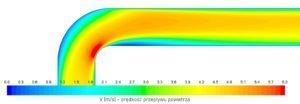
To fully understand the impact of an airflow disturbing component installed upstream of a regulator on the operation of the device, it is worth to first illustrate the flow of air through the most commonly used fittings, i.e. tees and bends:
The presented air flow analyses show how the disturbance of the air stream occurs while passing through the individual components of the system. In both cases the stream “sticks” to the upper wall of the duct. While in the case of the bend, the flow is stabilized after passing a distance of approx. 1.5 D from the curve, then for the tee the said distance is about 3 D. Due to a major flow disturbance by the inner edge of the component, at a distance of approx. 1 D nearly 80% of the total air flow amount is directed to the upper 50% of the duct. The location of the regulator at the presented distance disallows the proper operation of the device, let alone the applications where not a single straight section is used.
If the CAV regulator is installed at this distance, the air pressure working on the baffle is unevenly distributed. In view of the above, depending on the actual mounting method, the flow rate error can be either increased due to a larger opening of the baffle (e.g. if the mechanism is mounted facing the observer) or lowered due to the baffle being excessively closed (e.g. when the mechanism is mounted on the opposite side of the duct in relation to the observer’s position). In this case the best solution could be mounting the device with the mechanism facing up or down so that the baffle’s drive axle runs vertically. Still, this does not ensure the complete elimination of the problem. This mounting method will certainly minimize the control error because previously the airflow difference exerted different pressures on the individual halves of the control baffle perpendicularly to the baffle’s drive axle. However, at this point it should be emphasized that this manner of mounting has still not been recommended by manufacturers.
The above can apply to the VAV regulator including standard pressure increasing components, with a measuring strip or orifice. With such an uneven flow pattern, a pressure increasing component in the form of a single strip put horizontally could basically be bypassed completely by the main air stream. Consequently, the regulator opens the baffle wide to keep the desired flow rate. Simultaneously, the pressure increase on the strip would suggest that the regulator lets in an amount of air which is much smaller than actual. Modification of the calibration factor (the so-called K-factor), especially in the case of the tee, does not solve the problem either, since it is hard to determine the predictable characteristics. At lower flow rates, the stream is distributed faster in a laminar pattern over the entire duct cross section (which generates a pressure increase of a completely different nature), therefore the regulator lets in too little air.
The opposite happens at higher flow rates: in this case (due to the fact that the stream is “sticking” to the top part of the duct) the user may unknowingly cause the regulator to let through more air. In fact, the regulator would have to be set with two separate calibration factors. Yet another solution is to turn the regulator so that the strip is placed vertically (in addition, perforated sheet can be applied to cut the time for straightening the air stream). However, the perforated sheet generates major flow resistance and increased noise level, which is at times unacceptable – especially from the user’s point of view. Please note that only the manufacturer can modify the K-factor while maintaining the calibration procedures.
Having analysed the above, it can be stated that the second aspect to be considered is the type of a control mechanism and pressure increasing component. This is reflected into control accuracy and straight section application requirements. If a problem occurs, the error is eliminated by putting the pressure increasing component into the unit.
The correct calibration of regulators is essential. What else can disturb the work of regulators?
Elements that can disturb the flow before the regulator include tees, bends, diffusers, confusers, fittings, silencers (especially rectangular ones), flexible hoses, etc., that is components that may negatively influence the laminar flow pattern directly in front of the regulator. Unfortunately, contractors often think that these do not have a big impact (“it’s just a silencer”, “it’s just a reducer”, etc.). However, more often than not, in such cases the problem lies precisely in these elements. There are also instances where incorrect flow through the regulator generates more noise – both to the duct and to the environment. These issues contribute to the occurrence of problems with the acceptance of installations and the future comfort of such rooms.
It is also worth remembering that it is more beneficial to place the longer straight section in front of the regulator instead of keeping the required straight section behind the regulator at the expense of installing the straight section in front of it. A more advantageous solution in the event of a lack of space is to completely remove the straight section behind the regulator in order to extend the straight section in front of it, since the section in front of regulator has a greater impact on the correct operation of the flow regulators.
Improper calibration of regulators will not solve the problem
A frequent mistake made by fitters trying to “save” the building without the need of calling for the manufacturer’s service team is “calibrating” the regulator by correcting the Vnom value or changing the Vmin and Vmax operating range. These kinds of measures only serve as a temporary solution and — in the long run — allow at most accepting the building, but during its operation, users will repeatedly complain about insufficient ventilation. Such situations should be avoided as they cause more problems than benefits. The calibration of the regulators impacts the volume flow of air and the proper functioning of the device.
Calibration of regulators – how to avoid problems
In many cases, problematic situations can simply be avoided by using VAV regulators equipped with a Venturi tube, such as SMAY’s RVL-R. This device works correctly even when installed directly behind the tee, which is confirmed by both tests and CFD simulations. We have achieved this by performing numerous calculations, computer simulations and laboratory tests. These devices allow maintaining the best effectiveness of regulation in difficult building conditions. Moreover, thanks to the optimal shape of the tube, these products have the lowest flow velocities currently available in the market – from 0.45 m/s. This allows the installation of devices with larger diameters to be performed, which reduces the resistance of the installation. In this manner, we also obtain a lower sound power level emitted to the environment. Additionally, we facilitate installation by eliminating the need to mount straight sections upstream of the device.
The disturbance of flow and problems with ensuring the minimum pressure – serious errors in the mounting of regulators
A critical installation mistake is mounting VAV and CAV regulators in series. Sometimes contractors want to limit the operation of the VAV regulator, which has been incorrectly installed by them or calibrated on their own responsibility, by installing a CAV regulator behind it (often in-line to hide it from the view). Not only is this unjustified economically, but it also causes flow disturbances and problems with ensuring the minimum operating pressure required by the CAV device. If the VAV regulator is resistant, it may be caused by insufficient static pressure in the installation upstream of the CAV regulator. In such cases, it is advisable to seek help from the manufacturer.
Despite the growing awareness among designers, another type of a mistake is still present in systems. It is a combination of flow control through VAV or CAV regulators installed within one system with flow balancing in another branch – without the design taking into account any, even collective, regulator that would take over the flow changes generated by the air handling unit or the operation of VAV regulators. This mistake causes unpredictable airflows in rooms not covered by VAV or CAV regulators, and consequently, user discomfort when changing the performance of the AHU.
When designing and installing ventilation systems, it should be noted that specific building conditions require the use of appropriate devices. In case of unexpected situations, it is worth positioning the device in a way ensuring its greatest correct flow measurement possibilities. This will allow you to avoid many acceptance-related issues, and, at the same time, enable further convenient operation.
What should you take into consideration when installing ventilation systems and how to avoid mistakes when mounting regulators?
- Remember to correctly interpret the control error declared by the manufacturer.
- Select the proper devices to be installed within the system (it is reasonable to consider other aspects apart from the price).
- Keep the straight section upstream of the device as long as possible.
- If there is no minimum straight section length upstream of the device – analyse and determine the optimum installation manner.
- Do not tamper with the Vnom or K-factor setpoints. If necessary, call a service technician for recalibration.
- Avoid using regulators in the cascade arrangement.
- Design a consistent system; do not assume that the air will somehow “find its way”.
Autor

Michał Cisowski
VAV Systems Manager – SMAY


