Flow Resistance in Separated Stairshafts in Case of Fire

Can the pressure distribution in the stairshaft be predicted before the system is built and before field tests? Yes, it can! However, is it a simple task? Theoretically yes – the required patterns can be found in the literature, but as always, the devil’s in the detail.
In the case of low stairshafts, it can be assumed that the calculations made in accordance with the current PN-EN 12101-6 [1] standard will allow to obtain the assumed pressure distributions in the real object. The problem arises in high-rise buildings: the mentioned standard lists the factors influencing the pressure distribution in these buildings but does not specify how to take them into account at the design stage. One of them is the stack effect. The only recommendation of the standard in the context of this phenomenon suggests that if such a problem occurs in a building during acceptance tests, the stairshaft should be ventilated for one hour before the tests. However, is this approach correct for a system that should start during a fire? The answer to this question is unambiguous: NO – this is a wrong approach.
So how to approach the design of a pressure differentiation system in a high or high-rise building? The analysis of such cases should include not only the basic calculations specified in the design standard. It should also be extended with additional analyses based on technical knowledge, allowing for factors such as the stack effect or flow resistance to be taken into account. The analysis of these factors influencing the pressure distribution can be performed by means of CFD analyses or the use the analytical formulas given later in this Article.
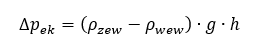
The value of the stack effect depends mainly on the height of the analysed space (h) and the gas density (ρ) depending on the difference between internal and external temperatures and can be determined from the following formula:
The flow resistance inside the stairshaft can be determined on the basis of the Darcy-Weisbach formula:
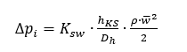
The above relationship is related to the value of the pressure drop (〖∆p〗_i) with the geometric dimensions of the stairshaft, the dimensionless coefficient of resistance (K_sw) and the air flow velocity (w). It can be assumed that the geometric information is known for a specific case.
The biggest problem when using the above formula is related to the determination of the flow resistance coefficient (K_sw). There is very little information in the literature about it, and most publications are based on single values from the research of Achakya and Tamura [2] [3], which resulted in the following values of the drag coefficient K_sw: for a stairshaft with a height of 2.6 m, the value is 71, and for a stairshaft with a height of 3.6 m it takes the value of 32. This is definitely too little data to determine the pressure losses in stairshafts of different geometry: its width, height, and the width of the stairs and landings may change.
Due to this, a series of tests was carried out to determine the resistance coefficients for different geometries of stairshafts. Encapsulated stairshafts of different heights, stair widths and different spacing between them were analysed.
The tests were carried out both on the real model of the stairshafts in the scale 1:10 and using CFD simulations. During the tests, an air flow was generated through the model of a stairshaft with a constant speed, and the pressure was read in various sections. The tests were aimed at determining the pressure drop per single storey of the stairshaft, and then, based on the knowledge of geometry and the average speed in the cross-section of the stairshaft, the resistance coefficients were determined (K_sw), using the transformed formula [2]. The studied model of the stairshaft and the corresponding numerical model, made in the Ansys Fluent program, are shown in Figure 1.
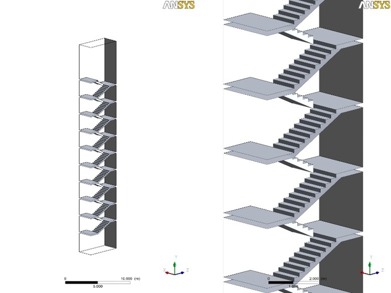

Figure 1. The tested numerical (a) and real (b) model of the stairshaft in 1:10 scale
The research was divided into several stages. One of them was to determine the influence of the handrail on the flow resistance. The analysis was performed both for the stairshaft without a handrail and for two variants of handrails of different designs. The model of the stairshaft with handrails is shown in Figure 2 and Figure 3.

Figure 2. The tested real model of the stairshaft with the handrail No. 1
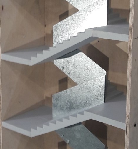
Figure 3. The tested real model of the stairshaft with the handrail No. 2
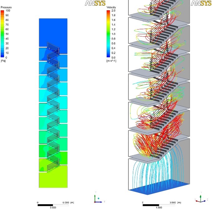
Figure 4. The results of the numerical analysis showing the pressure distribution (left) and the lines showing the air flow directions (right) in the stairshaft with handrail no.1
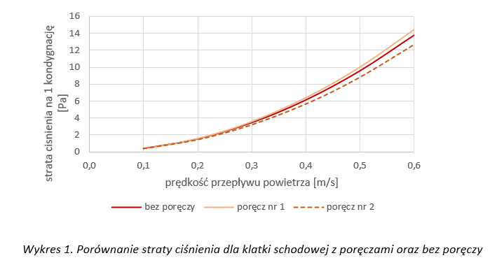
Graph 1. Comparison of pressure loss for a stairshaft with handrails and without handrails
Tests and simulations performed for various variants of the handrails, compared to their absence, showed that the presence of the handrails slightly influenced the obtained value of the pressure drop at the flow. Interestingly, the handrail No. 2 was characterized by the lowest resistance, i.e. it acted as a steering wheel that sets the direction of the flow and reduces the resistance.
In the next stage of the research, pressure drop analyses were performed for different widths of stairs and different heights of the stairshaft with a constant distance between the stairs (the clearance). This stage of research was carried out entirely using numerical analyses in the Ansys Fluent software. The dimensions of the tested geometries were selected on the basis of the requirements of the technical conditions [4] regarding the minimum usable widths of stairs and landings and the maximum heights of steps. Pursuant to these requirements, the minimum width of the flight of stairs in multi-family residential buildings and public utility buildings is 1.2 m, while in healthcare buildings it is 1.4 m. Based on the above information, stairs with a width of 1.2 m to 1.8 m were adopted. The change in the width of the stairs changed the width of the entire stairshaft. For example, a stairshaft with a stairs width of 1.2 m and a clearance of 0.1 m was 2.5 m wide, while a stairshaft with a stairs width of 1.5 m and a clearance of 0.5 m was 3.5 m wide, as in Graph 2.
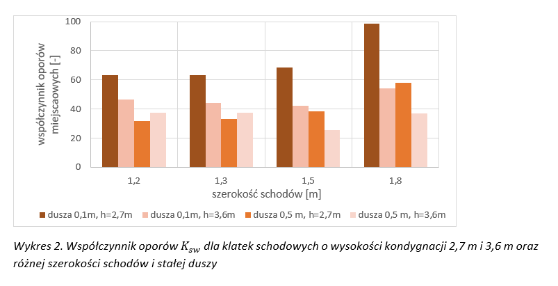
Graph 2. Resistance coefficient K_sw for stairshafts with a height of 2.7 m and 3.6 m and different width of the stairs and a constant clearance
One of the aims of the research was to determine how the stairshaft part with stairs influences the resulting resistances. The analyses were performed for the constant dimensions of the stairshaft walls 3.1 × 5.5 m and the storey height of 2.7 m. The stairshaft was tested with stairs of various widths (1.1 m to 1.5 m). As the width of the stairs decreased, the distance between them increased (i.e. the width of the so-called clearance increased). The results are shown in Graph 3.
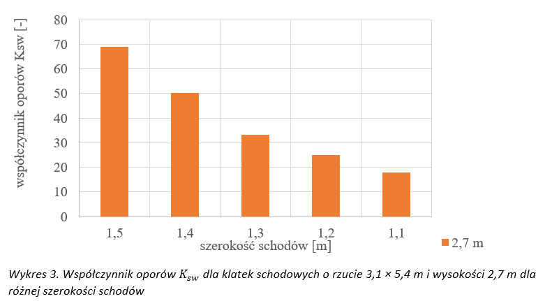
Graph 3. Resistance coefficientK_sw for stairshafts with a projection of 3.1 × 5.4 m and a height of 2.7 m for different widths of the stairs
As shown in diagram 3, the drag coefficient largely depends on the stairshaft filling the stairshaft space. Comparing the resistance for stairs 1.5 m and 1.2 m wide, it can be seen that wider stairs (and thus a smaller clearance) have almost three times more resistance than stairs with a smaller width (and greater clearance).
Interestingly, the earlier literature data provided for a stairshaft of similar height (2.6 m) only one value of the drag coefficient, equal to 71. As the results of the research have shown – the value of the resistance coefficient depends on many dimensions of the stairshaft and assuming its value only on the basis of the height is too much of a simplification. Comparing the obtained results for a stairshaft with a height of 2.7 m with the data from the literature for a height of 2.6 m, it can be seen that the value of the resistance coefficient equal to 71 can be assumed only for stairshafts with a length of 0.1 m, while for stairshafts with a wider clearance, the resistance coefficient should have much lower values. The adopted value of the resistance coefficient affects the value of resistance in the stairshaft, and thus translates into the size of the air stream needed to combat the stack effect in high and high-rise buildings. The knowledge of the resistance coefficients makes it possible to design fire ventilation systems more consciously, and therefore also to optimally select their parameters.
These studies were aimed at determining the resistance coefficients of stairshafts and were included in a wider scope in the doctoral dissertation Badanie oporów przepływu powietrza w wydzielonych pożarowo klatkach schodowych podczas działania wentylacji pożarowej (Testing air flow resistance in stairshafts separated by fire during fire ventilation operation), whose promoters were Ph. D Bogdan Mizieliński and Ph. D Eng. Grzegorz Kubicki [5], 2020 Politechnika Warszawska
Bibliography
[1] PN-EN 12101-6:2007 Systemy kontroli rozprzestrzeniania dymu i ciepła – Część 6 (Smoke and heat control systems – Part 6): Specification for pressure differential systems. Kits.
[2] G.Y. Achakji, G.T. Tamura, Pressure drop-characteristics of typical stairshafts in high-rise buildings, ASHRAE Transactions, 94/1, 1988, pp. 1223–1237.
[3] B. Mizieliński, G. Kubicki, Vntilation during a fire. Oddymianie (Smoke exhaust), Wydawnictwo Naukowe PWN, 2017.
[4] Regulation of the Minister of Infrastructure of 12th April 2002 on technical conditions to be met by buildings and their location, as amended.
[5] I. Tekielak-Skałka, Badanie oporów przepływu powietrza w wydzielonych pożarowo klatkach schodowych podczas działania wentylacji pożarowej (Testing air flow resistance in stairshafts separated by fire during fire ventilation operation), Dissertation, 2020.
Autor

Dr inż. Izabela Tekielak-Skałka

