Design Solutions for Overpressure Systems. Conformity to PN-EN 12101-6, Part III

Autor

Rafał Polichnowski
Assistant Commercial Director – SMAY Sp z o.o
Some time ago we analysed different design solutions for overpressure systems with a rate criterion of 2 m/s, in accordance with the PN-EN 12101-6 standard. We discussed three different variants:
• air supply directly to the stairwell, smoke exhaust from the zone engulfed in fire to the outside of the building, i.e. a gravitational system;
• air supply directly to the entrance hall, smoke exhaust from the zone engulfed in fire to the outside of the building, i.e. a gravitational system;
• air supply directly to the entrance hall, smoke exhaust from the zone engulfed in fire to the outside of the building, i.e. a mechanical system; smoke exhaust compensation by an opening in the wall between the entrance hall and the zone engulfed in fire.
Today, we are going to analyse yet another two variants. In the first case the entire air is supplied to the entrance hall (Figure 7). The air flowing at a rate of 14,400 m3/h passes through the doorway between the entrance hall and the zone engulfed in fire. Subsequently, the air is being transported out of the building by the provided smoke ventilation system. Smoke exhaust compensation with the door closed is ensured by an air supply system controlled by a pressure difference sensor equipped with a set of dampers and quick-acting actuators.
In the second case, the entire air is also supplied to the entrance hall. The air flowing at a rate of 14,400 m3/h passes through the doorway between the entrance hall and the zone engulfed in fire. Subsequently, the air is being transported out of the building by the provided smoke ventilation system. Smoke exhaust compensation with the door closed is ensured by an independent device that supplies air to the zone engulfed in fire.
First case, continued
d) Let’s assume that the entire air is being supplied to the entrance hall (Figure 7). The air flowing at a rate of 14,400 m3/h passes through the doorway between the entrance hall and the zone engulfed in fire. Subsequently, the air is being transported out of the building by the provided smoke ventilation system. Smoke exhaust compensation with the door closed is ensured by an air supply system controlled by a pressure difference sensor equipped with a set of dampers and quick-acting actuators. When the door is open, the air is being supplied to the entrance hall in order to ensure that the rate criterion of 2 m/s is met. However, when the door is closed, the air is being supplied directly to the zone engulfed in fire. Let’s analyse the resistance and system output generated with this airflow criterion.
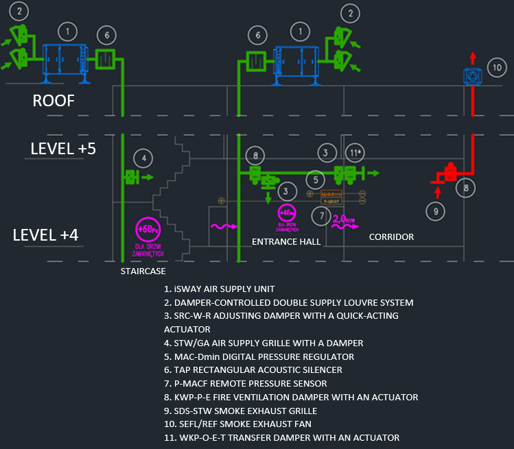
Figure 7. Air flowing through the doorway from one area to another.
The air flowing through the doorway from one zone to the other at a rate of 2 m/s generates a resistance of 6 Pa (Table 1). As we have a single doorway, the total resistance equals 6 Pa. We use mechanical exhaust ventilation. Therefore, no additional resistance is present in this case. The total resistance thus amounts to 6 Pa. We can state that all openings in the staircase require a resistance of at least 6 Pa so that the air passes through an open door in the direction of the exhaust grille of the smoke ventilation system.
The biggest opening in the staircase is an open emergency exit door outside the building. Let’s assume that its area is 2 m2. In order to ensure a flow resistance of 6 Pa, the airflow rate must equal 2.0 m/s. It seems that — considering that the air should flow to the staircase at a rate of 2 m/s — we must supply 14,400 m3/h (we shall not include any other leaks in the staircase in this analysis). Therefore, the total amount of air required to meet the airflow rate criterion with such a mechanical exhaust is 14,400 m3/h + 14,400 m3/h = 28,800 m3/h. Now, we should consider a proper placement of air supply points in the staircase in order not to exceed door opening force at any storey, i.e. 100 N. This also applies to the door in the entrance hall to the zone engulfed in fire. Air is supplied to the entrance hall and staircase by two independent devices.
ATTENTION! In case of the pressure difference criterion leaks in the staircase may be significantly lower (Figure 1). The fan must therefore supply extremely different quantities of air depending on the number of open and closed doors. Smoke exhaust compensation and entrance hall air supply are carried out by a single device. Its output rate is thus always 14,400 m3/h, regardless of whether the door is open or closed. Only devices with valid certificates stating fan working ranges and system response times should be used. Additionally, the smoke ventilation system for the zone engulfed in fire shall be designed for the output rate of 14,400 m3/h.
e). Let’s assume that the entire air is being supplied to the entrance hall (Figure 8). The air flowing at a rate of 14,400 m3/h passes through the doorway between the entrance hall and the zone engulfed in fire. Subsequently, the air is being transported out of the building by the provided smoke ventilation system. Smoke exhaust compensation with the door closed is ensured by an independent device that supplies air to the zone engulfed in fire. Air supply systems (both for the entrance hall and the zone engulfed in fire) have the same output rate, but they alternate and are regulated by a pressure difference sensor. When the door is open, the device supplies air to the entrance hall, ensuring that the rate criterion of 2 m/s is met, while when the door is closed, the amount of air is drastically lowered in order to meet the pressure difference criterion (Figure 1). At the same time, the device that supplies air for the purposes of smoke exhaust compensation provides the absolute minimum amount of air (door open) in order to drastically increase it to 14,400 m3/h (door closed). Let’s analyse the resistance and system output generated with this airflow criterion.
e). Zakładamy, że nawiew całości powietrza następuje do przedsionka (Rysunek 8). Powietrze o wydatku 14 400 m3/h przemieszcza się przez otwór drzwiowy pomiędzy przedsionkiem i strefą objętą pożarem. W dalszej kolejności zostaje przetransportowane na zewnątrz budynku przez zaprojektowany system oddymiania. Do kompensacji oddymiania przy zamkniętych drzwiach przewiduje się niezależne urządzenie nawiewne do strefy objętej pożarem. Systemy nawiewne (zarówno do przedsionka, jak i do strefy objętej pożarem) mają ten sam wydatek, lecz pracują naprzemiennie, a ich regulacja odbywa się od czujnika różnicy ciśnień. Gdy drzwi są otwarte, urządzenie nawiewa powietrze do przedsionka, realizując kryterium przepływu 2 m/s, natomiast przy drzwiach zamkniętych ilość powietrza gwałtownie maleje, aby spełnić kryterium różnicy ciśnień (rysunek 1). W tym samym czasie urządzenie dostarczające powietrze do kompensacji oddymiania nawiewa minimalną ilość powietrza (otwarte drzwi), aby gwałtownie ją zwiększyć do 14 400 m3/h (zamknięte drzwi). Przeanalizujmy więc, jaki jest generowany opór i wydatek systemu przy tak realizowanym kryterium przepływu.
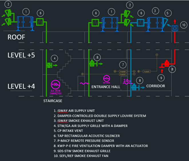
Figure 8. Air flowing through the doorway from one area to another
The air flowing through the doorway from one zone to the other at a rate of 2 m/s generates a resistance of 6 Pa (Table 1). As we have a single doorway, the total resistance equals 6 Pa. We use mechanical exhaust ventilation. Therefore, no additional resistance is present in this case. The total resistance thus amounts to 6 Pa. We can state that all openings in the staircase require a resistance of at least 6 Pa so that the air passes through an open door in the direction of the exhaust grille of the smoke ventilation system.
The biggest opening in the staircase is an open emergency exit door outside the building. Let’s assume that its area is 2 m2. In order to ensure a flow resistance of 6 Pa, the airflow rate must equal 2.0 m/s. It seems that — considering that the air should flow to the staircase at a rate of 2 m/s — we must supply 14,400 m3/h (we shall not include any other leaks in the staircase in this analysis). Therefore, the total amount of air required to meet the airflow rate criterion with such a mechanical supply and exhaust is 14,400 m3/h + 14,400 m3/h + 14,400 m3/h = 43,200 m3/h. Now, we should consider a proper placement of air supply points in the staircase in order not to exceed door opening force at any storey, i.e. 100 N. This also applies to the door in the entrance hall to the zone engulfed in fire. Air is supplied to the entrance hall and staircase by two independent devices.
ATTENTION! In case of the pressure difference criterion leaks in the staircase may be significantly lower (Figure 1). The fan must therefore supply extremely different quantities of air depending on the number of open and closed doors. Only devices with valid certificates stating fan working ranges and system response times should be used. Additionally, the smoke ventilation system for the zone engulfed in fire shall be designed for the output rate of 14,400 m3/h.
Conclusion:
In order to ensure the rate criterion of 2 m/s by means of gravitational exhaust ventilation, the following should be taken into consideration: the bigger the resistance of air flowing from the stairwell/entrance hall in the direction of the exhaust located outside the building, the bigger the output rate of devices that supply air.
In order to ensure the rate criterion of 2 m/s by means of mechanical exhaust ventilation, the following rule should be followed: the underpressure in the zone engulfed in fire should be as low as possible due to the fact that the force vectors applied to the closed door between the underpressure and overpressure zones add up. As the door surface, closer setpoint and door handle location may differ, we suggest making calculations that would confirm the door opening force of not more than 100 N.
Safety Way: an innovative differential pressure system – escape routes free from smoke and fire – highest degree of protection.
The Safety Way differential pressure system is a solution designed for multi-storey buildings:
• iSWAY-FC® differential pressure product for smoke and heat control systems;
• Innovative predictive algorithm;
• Anti-Frost system that endures even the most extreme weather conditions;
• 24-hour automatic test of all the components;
• Automatic adaptation to changing service conditions;
• Communication between individual components of the set and continuous tracking of all components (regulators, remote pressure sensors, etc.);
• Continuous measurement of the set value of static differential pressure between the protected and reference zones by the P-MAC(F) sensor.
Do you want to know more? Visit our BLOG. Our experts will provide you with a full knowledge base on ventilation and fire protection.
Do you need advice? Contact our advisor department.

